Meniscus Matching

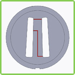
Meniscus matching centerpieces are used to ensure that the meniscus location of the fluid in the reference channel, (left side) and sample channel (right side) are identical.
Meniscus matching centerpieces are available only in a 12mm path length. MM centerpieces can be ordered with either the Spin50 or Spin60 base geometry.
Our custom designed meniscus matching centerpiece has two capillary grooves in the top face of the centerpiece. The Z-shaped groove is the fluid transfer channel while the straight groove at the top of the channels is for pressure relief as the fluid transfers from the reference to the sample side of the centerpiece.
When properly loaded, fluid from the reference side (left) will transfer through the fluid transfer groove at rotor speeds between 3,000 rpm and 10,000 rpm but should not transfer below 3,000 rpm (or standing on the bench). The fluid will transfer until the menisci are the same in the sample and reference sides.
Parts and Pricing
| Product Description | Path Length | Part# |
| Spin50-MM | 12mm | SACP205 |
| Spin60-MM | 12mm | SACP105 |
This item is now available from Nanolytics Instruments.
Loading Procedure
When loading meniscus matching centerpieces, use either 23 Ga stainless steel blunt end syringe tip (Small Parts P/N NE-231PL-25) or a gel loading tip with capillary end (VWR 37001-150). Do not use a standard pipette tip because the tip can seal the fill hole opening resulting in a pressure seal. If this occurs the sample will be forced through the capillary grooves during filling and some fluid will bubble out of the fill hole.- Install bottom window assembly into cell housing.
- Install the MM centerpiece into cell assembly with the capillary channels facing up (toward threaded end of cell housing).
- Install top window assembly, screw ring gasket, and screw ring.
- Using torque stand tighten the screw ring to 130-140 in-lbs.
- Load the sample + buffer into the right side channel (load volume ~325 uL for Spin60-MM and uL for Spin50-MM centerpieces.
- Install fill hole gasket and fill hole screw in sample side channel.
- Load buffer into the reference side of the centerpiece. The fill volume should be 350-375 uL but should not fill the channel so full that it covers the straight pressure relief capillary at the top of the channel.
- Install the fill hole gasket and fill hole screw in the reference side channel.


